


THE FIRERAY ONE
|
Add to My Constguide favorites
 THE FIRERAY ONE
|
Description
Detection performance Alarm response threshold levels 25% (1.25dB) – Fastest response to smoke User features Electrical specifications Field wiringDescription
35% (1.87dB) – Default value
55% (3.46dB) – High immunity to false alarms, slow response to smoke
85% (8.23dB) – Highest immunity to false alarms, slowest response to smoke
Confi gured via the integrated user interface
Delay to Alarm 10 seconds, for momentary partial obstruction of the beam path
Delay to Fault 10 seconds, for momentary obstruction of the beam path
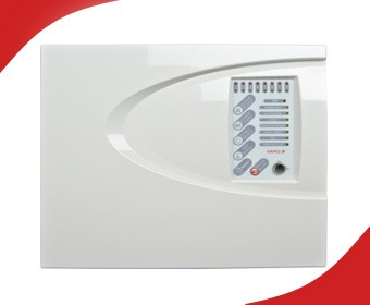
Integrated user interface Alignment mode switch, alignment directional buttons and confi guration switches for alarm
response threshold
Alignment status indication 2 Green LEDs and 1 Yellow LED
System status indication Normal operation – Green LED fl ashing every 10 seconds
Alarm condition – Red LED fl ashing every 10 seconds
Fault condition – Yellow LED fl ashing every 10 seconds for obscuration or every 5 seconds
Approvals
UL268
0832-CPR-F2237
Design parameters
The separation distance between Detector and Refl ector 5 to 50m
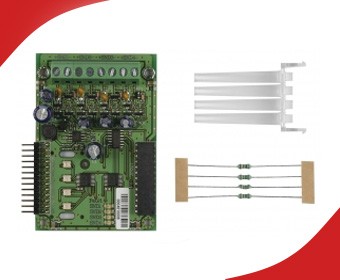
50 to 120m with Refl ective Long Range Kit
Beam path clearance 1m in diameter from centre line between Detector and Refl ector
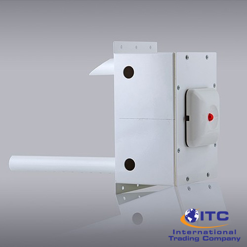
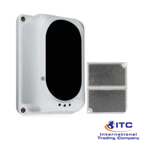
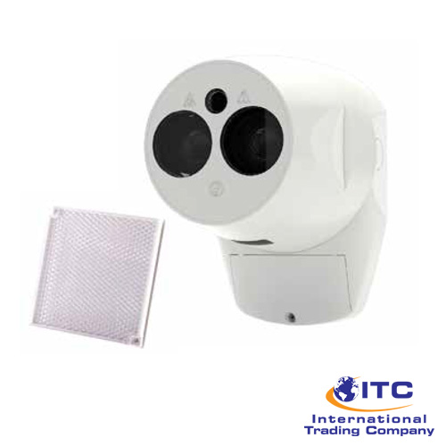
Detector dimensions Width 130mm x Height 181mm x Depth 134mm (see diagram)
Refl ector dimensions Up to 50m separation distance – Single refl ector 100mm x 100mm x 9mm
Up to 120m separation distance – Four refl ectors arranged in a square pattern 200mm x 200mm x 9mm
Product weight Detector – 0.7kg; Reflector – 0.1kg
Multi-detector arrangement Dynamic Beam Phasing allows for Detectors to face each other with the refl ectors in the middle
Housing colour White RAL9016, UV stable
Operating voltage 14 to 36 VDC
Operating current (constant) all operational modes All operational modes – 5mA; Fast alignment mode – 33mA
Cable gauge and type 2 core, dedicated, 0.5 to 1.6mm (24 to 14 AWG)
System compatible with fi reproof and non-fi reproof cable meeting local installation standards
Cable entry 3 knock-out locations capable of accepting M20, ½” or ¾” glands
4 drill-out locations capable of accepting glands up to 21mm diameter